Drawing Circuit Diagram From Boolean Expression
Download the Notes
TOPIC 1: Logic Representation
There are 3 common means in which to represent logic.
i. Truth Tables
ii. Logic Circuit Diagram
3. Boolean Expression
We will hash out each herein and demonstrate ways to convert between them.
TOPIC 2: Truth Tables
A truth tabular array is a nautical chart of 1s and 0s bundled to indicate the results (or outputs) of all possible inputs. The list of all possible inputs are bundled in columns on the left and the resulting outputs are listed in columns on the right. There are 2 to the power north possible states (or combination of inputs). For example with three inputs there are ii^3=8 possible combination of inputs. (Audio)

TOPIC iii: Logic Diagram
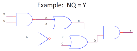
A logic diagram uses the pictoral description of logic gates in combination to represent a logic expression. An case below shows a logic diagram with iii inputs (A, B, and C) and 1 output (Y). The interpretation of this will become clear in the following sections.
 TOPIC four: Boolean Expression
Boolean Algebra can be used to write a logic expression in equation form. In that location are a few symbols that you lot'll recognize but need to redefine.
 Notation: Sometimes when the ! is used to represent the Non it is used before the letter and sometimes it is used after the letter of the alphabet. Care should be used so that yous understand which method is existence used!
Below is an case boolean expression. In fact, it represents the same logic every bit the example logic circuit diagram above. This concept volition also become clearer when nosotros cover converting from and to the boolean expression below.
 TOPIC five: Converting from a Logic Circuit Diagram to a Truth Table
This conversion is achieved by selecting each state (or combination of inputs) one at a fourth dimension, replacing the inputs with their respective values and figuring the value of each point through the circuit until the output is reached. The final output value for each state is so listed in the truth table next to the value of each input. Below is a logic circuit diagram with the input values. Written report it carefully for an extended period of time, it is an animated epitome and the inputs and output will change every few seconds. (Click the image if it isn't irresolute) Below are the results of the conversion in truth table form.
TOPIC 6: Converting Logic Excursion Diagrams to Boolean Expressions
To catechumen from a logic circuit diagram to a boolean expression we start by listing our inputs at the correct identify and process the inputs through the gates, 1 gate at a time, writing the consequence at each gate'due south output. The following is the resulting boolean expression of each of the gates.
And here is an example of the process being carried out. The fact that the result simplifies to the XOR is simply coincidental. (Audio)

 TOPIC 7: Converting Truth Tables to Boolean Expressions
There are 2 methods for converting truth tables to boolean expressions.
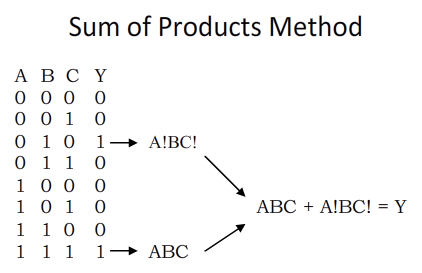
The Sum of Products (Sound)
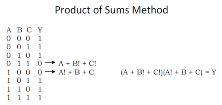
 The Product of Sums (Sound)

TOPIC viii: Converting Boolean Expressions to Logic Diagrams
Converting boolean expressions to logic diagrams is the most challenging conversion on this page because information technology requires a very expert understanding of guild of operation. Beneath is the order of operations used in this conversion. (Sound)
 In club to complete this conversion we will progress through the order of operations. We will first await for bracketed quantities or something in parentheses. Inside any parentheses nosotros will look for more parentheses and then NOTs, then ANDs, so ORs. It'southward best to begin with an example.
Audio
 Sound
Sound Sound
Sound Sound
Sound Audio
Audio TOPIC nine: Converting a Truth Tabular array to a Logic Diagram
The easiest way to achieve this is to first convert the truth table to a boolean expression and so to a logic diagram.
You should at present be prepared to answer the post-obit questions. Click here for Webct.
1. A logic organisation has five inputs. How many possible states be in this system?
2. What symbol is used to represent the Not gate when the line over the alphabetic character is not convenient to use?
3. A logic system has three inputs and therefore viii possible states. The logic diagram representation is shown below. Complete the truth table and convert the output column to hexadecimal if the state 0 is the to the lowest degree pregnant flake and the country 7 is the most significant bit.
 4. Give the boolean expression from the in a higher place circuit diagram.
5. A truth table has the same states as in number iii above. However, the output column from superlative to bottom reads 00110101. Give the result of the sum of products method.
6. Give the outcome of the production of sums method in number 5 higher up.
vii. A boolean expression is given Y = (A+B)C+!BA+!C(A+B)+!(Air-conditioning). Just as in 3 above, produce a truth table and convert the output column to hexadecimal.
Source: https://drstienecker.com/tech-332/3-logic-circuits-boolean-algebra-and-truth-tables/
0 Response to "Drawing Circuit Diagram From Boolean Expression"
Enregistrer un commentaire